meta name="google-site-verification" content="qPXq3ng3Un-JLJJS-khGL63_pLtt-xAG2GutG_0hnGE" />

Wednesday, December 8, 2010

Project 3 Step 2

Step 2

I'm going to begin this step by going back to the shank I created in step one and change the shape in the center of the ring. I want that area to be straight and not pointed. After that I will create a rectangle vector that I will subtract from the profile vector to make a euro shank. I simply reset the relief and then re sweep with the changed vectors to build my final ring design.

3D view showing the pointed section in the center of the ring.


2D view of the section I am going to edit.


I reset the relief then mirror the rectangle to use as a guide for editing.


Editing the top rail by inserting nodes.


Mirroring the edited top rail to the bottom.


Making a rectangle vector in the profile section for the euro shank.


F9 the rectangle to make sure it is centered. Then use the down arrow key to nudge in place.


The rectangle is in position


Subtract the rectangle from the profile vector by selecting the ring profile first, holding down shift and selecting the box second. Press the subtract vectors button.


This is the result. I will now edit the profile to the euro shape.


Enter node editing by pressing "n" and create an arc at the bottom by pressing "a".

.
Raise the arc vector up and then select the two outer nodes and nudge them down. Adjust the arc as needed for a pleasant design.


Two rail ring sweep the vectors. Select the top rail, bottom rail, small cross section, large cross section, and ring profile, in that order by holding down the shift key. Press the Two Rail Ring Sweep button to get to this menu. Make sure the add button is selected then press calculate.


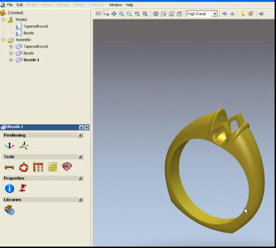
The result from the sweep showing the euro and removed pointed section in the center of the ring. I still need to add the ridge back. 


Select the two rectangle shapes and use the shape editor to add the 90 degree dome ridge back to the shank. Now, mirror merge left to right to assure both side are the same.


The finished shank design.


 The Euro Shank Video

Tuesday, December 7, 2010

Project 3 Step 3

Step 3

This step builds a pear shape bezel in the 3 axis flat. The stone size is 4 X 3. I begin by making a rectangle vector the size of the pear shape stone and then place a 3mm circle at the bottom. The rectangle serves as a guide for my stone. I edit the circle into the pear shape. I then offset the stone vector outward and inner .35mm to create the bezel walls and the inner opening. I F12 and add 1.5mm to the outside vector. Then add a -45 degree pyramid with a start height of -.5mm. The inner vector is zeroed. This creates the bezel that is added to the assembly by the mesh creator.

The flat three axis model is used for the bezel. A small model size is used to just accommodate the setting.


Draw a 3 X4 guide box to create the bezel setting.


Draw a 3 mm circle and select the circle first then the rectangle then click align bottom.


Node edit the circle into a pear shape using the rectangle as a guide.


 Offset the stone vector both inner and outer by .35mm


Using F12 add 1.5mm to the outside vector.


Using F12 add a -45 pyramid with a -.5 Start Height to the stone vector.


Using F12 zero the inner vector.


Add to the assembly with the mesh creator.


Rotate and nudge into position.


Copy and paste another bezel into the assembly.


Rotate the second bezel 180 degrees in z.


The completed ring.


 The Pear Shape Bezels Video


Project 3 Euro Shank


This is a simple design with many possible ways to recreate it differently. It is designed to fit a half carat center diamond set in a peg head. Two 4 X 3 pear shape stones are placed as accents on the side. It also has a euro shank for both looks and comfort.


Step 1


 Select the Tapered Round Shank from the model New Shanks section. The following pictures show the values entered.


This is the view showing a thick and not very flowing shank design created by the wizard. I am going to edit this model into my final shape. The important thing to remember during the design process is to create smooth flowing lines and pleasing shapes.


The first thing to do is accept the wizard, then reset the relief, then offset the inner shank in the profile section out by 1.8mm. The thickness of 1.8mm between the fingers keeps the ring comfortable. This will be the vector I will edit to make the ring profile including the euro shank later. Normally, I would do all the editing in one step but to demonstrate the thinking process I have broke it down in smaller sequences. 


The next thing to do is edit the profile curve into our desired shape. This is done by node editing. I also inserted a couple of nodes to create the profile I wanted.


This is the view of the shank after editing in the profile section.


Here I am editing the top rail for the ring shank. I only reshape the top left side. I will delete the bottom rail and then mirror the edited top rail to the bottom. 


A two rail ring sweep is done with the changed vectors including the profile or ring silhouette.


This is the result of the ring sweep and a mirror merge left to right.


A rectangle vector is added to the shank where we want to make a ridge for decoration. This rectangle needs to be node edited to match the shape of the rails.


Use the shape editor F12 to add a domed 90 degree height to our vector.

The result is then mirror merged left to right to get both sides of the ring.


The 2D view of the completed shank.


The Shank Video

Tuesday, November 30, 2010

Stuller Settings Catalog

If you are a member of the verified section of the ArtCam forum I have uploaded a selection of Stuller settings that can be downloaded and added to the component library. The link to the download and the original post is located here at the ArtCam Forum . You can also use this link to  Download the settings too. Afterwords, just go to ArtCam files/component libraries/Settings and add this folder, then do a rescan and they will be available to import. Here is a picture of all 18 settings.

 Stuller Settings

These make a nice presentation to add to your finished ArtCam projects. You will still need to scale the settings to fit the required stone size you need. The setting numbers are the catalog numbers from the Stuller findings catalog to make for easy ordering of the part. Here is number 383 for example used as the center head for project 2. 


Enjoy the download.


Project 2 Step 5

Step 5

In this section I am going to create the engagement ring by duplicating the wedding band model and then editing the vectors. This is a very quick way to produce this ring. I can do this by drawing a rectangle vector where I want to merge low 1.5mm the center of the ring for a peg head to be soldered on. I will also ungroup the vectors to remove the unwanted vectors and then regroup only the vectors I need.


Merge Low Center Section


Project 2 Step 4


Step 4

In this section I am going to create the milligrain beads to place on the outside edge of the ring. These beads are .4mm in diameter and spaced .15mm apart. They are also doomed at 45 degrees. This spacing works well because they are still close enough to each other for a pleasing effect and yet far enough apart to allow the mill to cut between each one without damage or distorting  the beads.  I will offset the shadow box .4mm and edit that box to get the line that I can paste the beads on to evenly. After that I will apply the shape editor (F12) to all the vectors I have drawn to build the finished wedding band from the blank. 

Milligrain Beading


The Milligrain and Wedding Band Completion Video


Project 2 Step 3

Step 3
In this section I am going to make the beads for setting the stones and the recessed shadow box around the diamonds. I have selected .6mm as the diameter of the beads. I place the first one in position and then holding down the control key and hitting C then V to copy and paste a new bead. Using the arrow keys I then move the new bead into position. The zoom button also allows for great accuracy in placing these beads into their proper position. The shadow box is created by editing a rectangle around the stones/beads closely and then offsetting by .4mm. I have found a .4mm space allows for easy polishing around the beads.


Beads and Shadow Box Video


Monday, November 29, 2010

Project 2 Step 2

Step 2

In this section I am going to make the vectors for the diamonds. I will make the first stone at 2.0mm then offset that stone larger by .15mm. I offset the stone because we need a tolerance for stone size variations  and to make sure they do not touch each other when setting the finished ring. It also serves as a guide to align adjacent stones. I  then select both circles by holding down the shift key and clicking each one till highlighted and then copy and paste a second set of circles. Using the left arrow key and the zoom button I then align the outside circles to each other. By selecting both sets of these now aligned circles and hitting the F9 key I will accurately center the pair. I do this because we have an even number of stones and therefore there is no stone centered in the ring. 

I then continue to create each stone one at a time, offset the .15mm and align them up until all required stones are completed. I will only do half the ring because I will mirror the rest of the design later. 


Stone Vectors
 Stone Vectors Video